The following table provides a list of the logic controls and a brief description of each control’s function. Click a control name to see more detailed information.
|
Control Name |
Description |
|
Accepts two inputs. Outputs the absolute value of the difference between the input values. | |
|
Accepts one input. Outputs the absolute value of the input value. | |
|
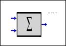
Accepts two or more inputs. Outputs the sum of the input values. | |
|
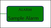
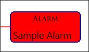
Accepts one input. If the input provides an alarm condition of false, then this control will turn green to indicate an alarm state has not occurred. If the input provides an alarm condition of true, then this control will turn red to indicate an alarm state has occurred. | |
|
Accepts two or more inputs. If all inputs provide an alarm condition of true, then the output is true. If one or more inputs provide an alarm condition of false, then the output is false. | |
|
Accepts two or more inputs. Outputs the average of the input values. | |
|
Accepts one input. In the control’s configuration, specify a low value and a high value. If the input value is lower than the low value, outputs the low value. If the input value is higher than the high value, outputs the high value. If the input value is between the low value and the high value, outputs the input value. | |
|
Accepts a manually entered value as the input. Outputs the specified constant value. Double-click the control to specify a value for the output. | |
|
Accepts one input. If the input provides an alarm condition of true and the delay control has a specified On Delay, then the output will be an alarm condition of false until the delay time has elapsed. If the input changes from an alarm condition of true to an alarm condition of false and the delay control has a specified Off Delay, then the output will be an alarm condition of true until the delay time has elapsed. | |
|
Accepts a digital text tag as the input value. Drag and drop the digital text tag onto the control. If the input value matches the specified compare value, then the output is an alarm condition of true. | |
|
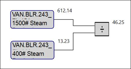
Accepts two inputs. Output is the quotient of the inputs. By default the first (top/A) input is the dividend, and the second (bottom/B) input is the divisor. | |
|
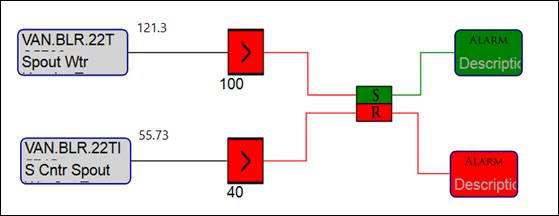
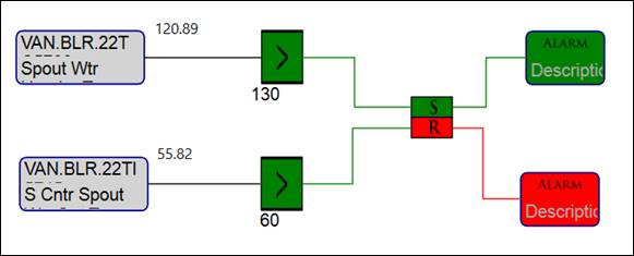
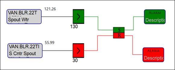
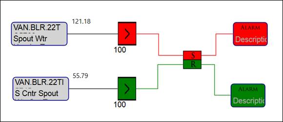
Accepts two inputs, S and R. If both inputs provide an alarm condition of true, then S outputs an alarm condition of false and R outputs an alarm condition of true. If both inputs provide an alarm condition of false, then S outputs an alarm condition of false and R outputs an alarm condition of true. If the S input provides an alarm condition of false and the R input provides an alarm condition of true, then S outputs an alarm condition of false and R outputs an alarm condition of true. If the S input provides an alarm condition of true and the R input provides an alarm condition of false, then S outputs an alarm condition of true and R outputs an alarm condition of false. | |
|
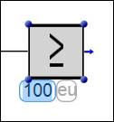
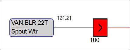
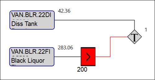
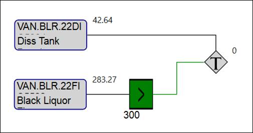
Accepts one input. If the input value is greater than or equal to the specified compare value, then the output is an alarm condition of true. | |
|
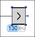
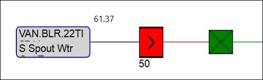
Accepts one input. If the input value is greater than the specified compare value, then the output is an alarm condition of true. | |
|
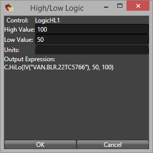
If the input value is higher than the specified High Value or lower than the specified Low Value, then the output is an alarm condition of true. | |
|
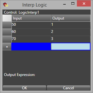
Accepts one input. Outputs an interpolated value based on the criteria specified in the control’s configuration. | |
|
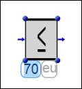
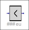
Accepts one input. If the input value is less than or equal to the specified compare value, then the output is an alarm condition of true. | |
|
Accepts one input. If the input value is less than the specified compare value, then the output is an alarm condition of true. | |
|
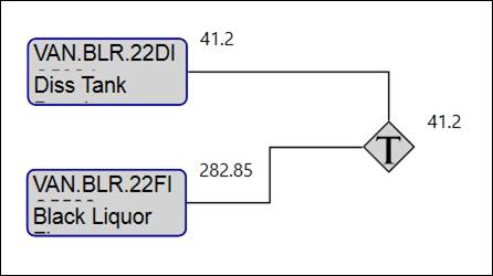
Accepts two or more inputs. Outputs the maximum input value. | |
|
Accepts two or more inputs. Outputs the maximum input value. | |
|
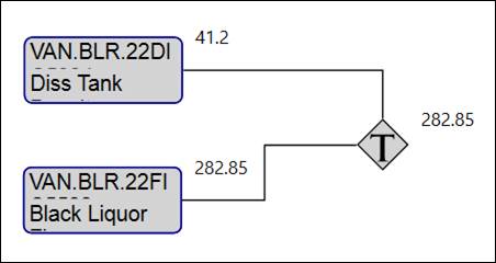
Accepts two or more inputs. Outputs the minimum input value. | |
|
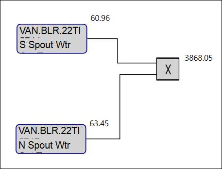
Accepts two inputs. Output is the product of the inputs. | |
|
Accepts one input. If the input value provides an alarm condition of true, then outputs an alarm condition of false. If the input value provides an alarm condition of false, then outputs an alarm condition of true. | |
|
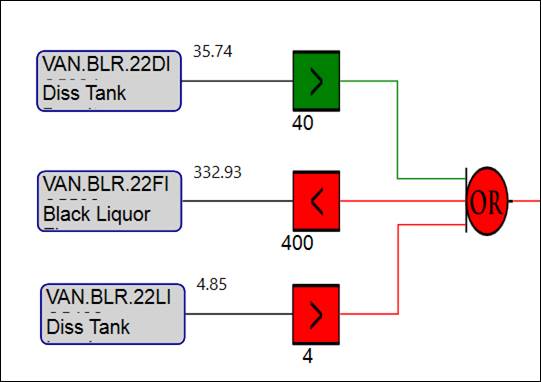
Accepts two or more inputs. If at least one input provides an alarm condition of true, then the output is an alarm condition of true. If all inputs provide an alarm condition of false, then the output is an alarm condition of false. | |
|
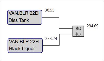
Accepts two or more inputs. Outputs the difference between the maximum value and the minimum value. | |
|
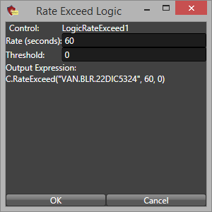
Accepts one input. If the rate of change (slope) of the input value exceeds the specified threshold, then the output is an alarm condition of true. | |
|
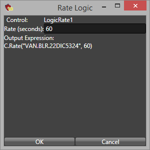
Accepts one input. Outputs the rate of change (slope) of the input value using a best fit statistical method. | |
|
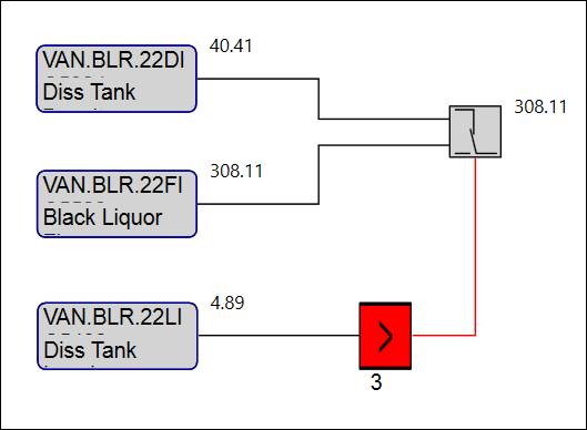
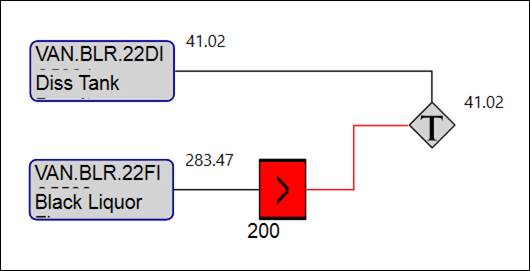
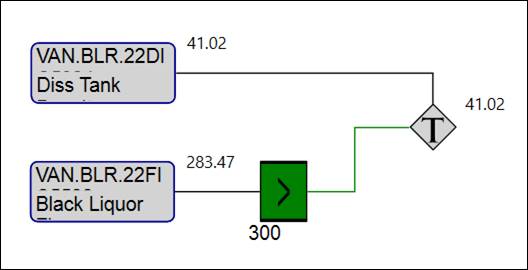
Accepts three inputs, A, B, and C. If input C provides an alarm condition of true, then the output is the value of input B. If input C provides an alarm condition of false, then the output is the value of input A. | |
|
Accepts two inputs. Output is the difference of the inputs. By default the first (top/A) input is the minuend, and the second (bottom/B) input is the subtrahend. | |
|
Accepts two or more inputs. Output is the sum of the inputs. The input sign can be specified in the control’s configuration. | |
|
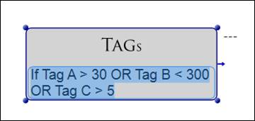
Accepts two or more tag values as the inputs. Drag and drop multiple tags onto the control. If the expression defined in the control’s configuration evaluates to true, then the output is an alarm condition of true. If the expression defined in the control’s configuration evaluates to false, then the output is an alarm condition of false. | |
|
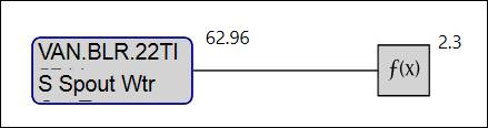
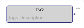
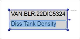
Accepts one tag value as the input. Drag and drop the tag onto the control. Output is the tag’s value. | |
|
Accepts two inputs, A and B. An expression must be specified in the control’s configuration. If the expression evaluates to true, then the output is input A. If the expression evaluates to false, then the output is input B. If the input value is numeric, then the output is numeric. If the input value is an alarm condition, then the output is an alarm condition. |
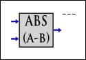
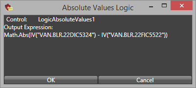
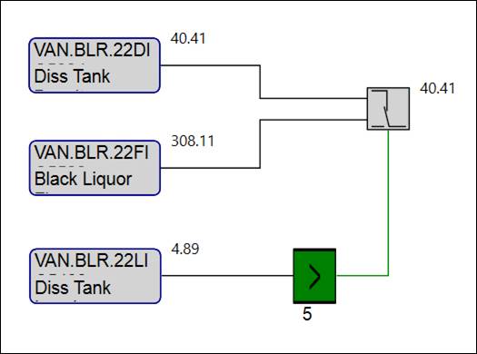
Description: Accepts two inputs. Outputs the absolute value of the difference between the input values.
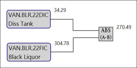
Configuration: After two logic controls have been configured and connected to the Abs Vals control, shows the resultant expression. The logic cannot be modified here.
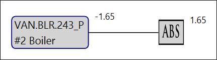
Description: Accepts one input. Outputs the absolute value of the input value.
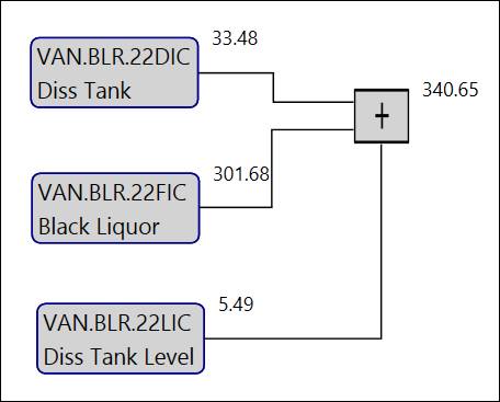
Description: Accepts two or more inputs. Outputs the sum of the input values.
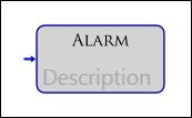
Description: Accepts one input. If the input provides an alarm condition of false, then this control will turn green to indicate an alarm state has not occurred. If the input provides an alarm condition of true, then this control will turn red to indicate an alarm state has occurred.
Double-click the control to edit the alarm control’s description. Note that this is not the description of the alarm definition.
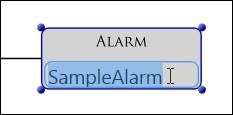
Configuration: After an input that provides an alarm condition has been configured, shows the properties of the resultant alarm definition and the expression used to calculate the alarm condition. Initially the alarm will not have a name. The name can be specified here or in the Logic Design Manager.
After a name has been entered, the names of the CALC-source tag and the Alarm tag that will be created will populate.
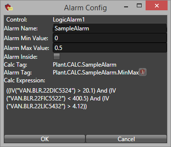
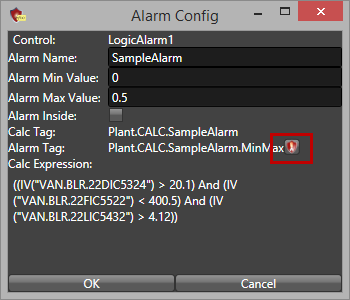
The alarm will not be created until it is saved in the Logic Design Manager. Once it has been saved, click the alarm icon to open Alarm Configuration and view the alarm definition’s full details.
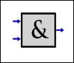
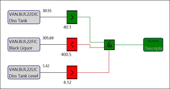
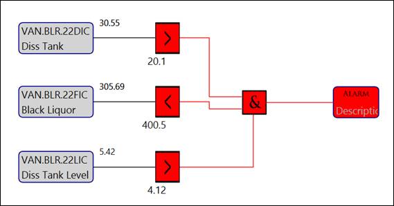
Description: Accepts two or more inputs. If all inputs provide an alarm condition of true, then the output is true. If one or more inputs provide an alarm condition of false, then the output is false.
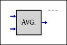
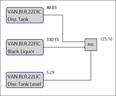
Description: Accepts two or more inputs. Outputs the average of the input values.
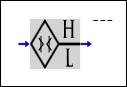
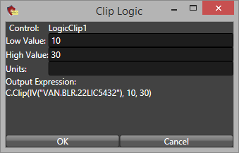
Description: Accepts one input. In the control’s configuration, specify a low value and a high value. If the input value is lower than the low value, outputs the low value. If the input value is higher than the high value, outputs the high value. If the input value is between the low value and the high value, outputs the input value.
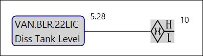
Configuration: Specify the low value and high value.
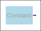
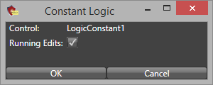
Constant: Accepts a manually entered value as the input. Outputs the specified constant value. Double-click the control to specify a value for the output.
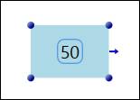
Configuration: Choose whether to allow the value of the constant to be edited from the running PARCgraphics display.
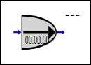
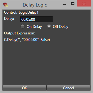
Description: Accepts one input. If the input provides an alarm condition of true and the delay control has a specified On Delay, then the output will be an alarm condition of false until the delay time has elapsed. If the input changes from an alarm condition of true to an alarm condition of false and the delay control has a specified Off Delay, then the output will be an alarm condition of true until the delay time has elapsed.
Configuration: Choose whether to specify an On Delay or an Off Delay, and then specify a delay time. The syntax is: HH:mm:ss.
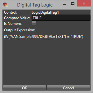
Description: Accepts a digital text tag as the input value. Drag and drop the digital text tag onto the control. If the input value matches the specified compare value, then the output is an alarm condition of true.
Configuration: Specify the compare value and whether the numeric or text input should be used. The compare value must exactly match the input value for the alarm condition to be true.
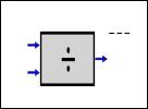
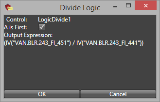
Description: Accepts two inputs. Output is the quotient of the inputs. By default the first (top/A) input is the dividend, and the second (bottom/B) input is the divisor.
Configuration: Specify whether the first input is the dividend or the divisor.
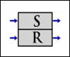
Description: Accepts two inputs, S and R. If both inputs provide an alarm condition of true, then S outputs an alarm condition of false and R outputs an alarm condition of true. If both inputs provide an alarm condition of false, then S outputs an alarm condition of false and R outputs an alarm condition of true. If the S input provides an alarm condition of false and the R input provides an alarm condition of true, then S outputs an alarm condition of false and R outputs an alarm condition of true. If the S input provides an alarm condition of true and the R input provides an alarm condition of false, then S outputs an alarm condition of true and R outputs an alarm condition of false.
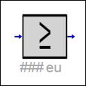
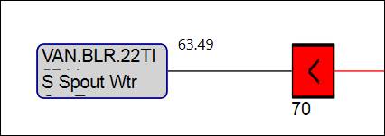
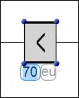
Description: Accepts one input. If the input value is greater than or equal to the specified compare value, then the output is an alarm condition of true.
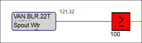
Double-click the control to specify the compare value and engineering units (optional).
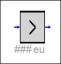
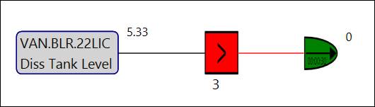
Description: Accepts one input. If the input value is greater than the specified compare value, then the output is an alarm condition of true.
Double-click the control to specify the compare value and engineering units (optional).
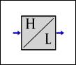
Description: If the input value is higher than the specified High Value or lower than the specified Low Value, then the output is an alarm condition of true.
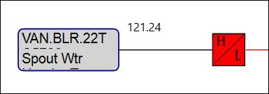
Configuration: Specify the High Value, Low Value, and Units (optional).
Description: Accepts one input. Outputs an interpolated value based on the criteria specified in the control’s configuration.
Configuration: Specify input values and the corresponding output values to be used when calculating the interpolated value.
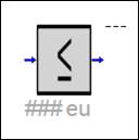
Description: Accepts one input. If the input value is less than or equal to the specified compare value, then the output is an alarm condition of true.
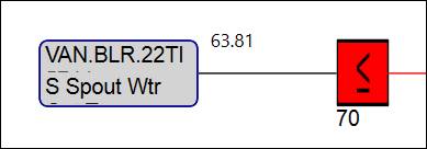
Double-click the control to specify the compare value and engineering units (optional).
Description: Accepts one input. If the input value is less than the specified compare value, then the output is an alarm condition of true.
Double-click the control to specify the compare value and engineering units (optional).
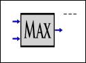
Description: Accepts two or more inputs. Outputs the maximum input value.
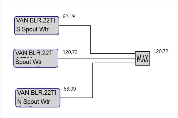
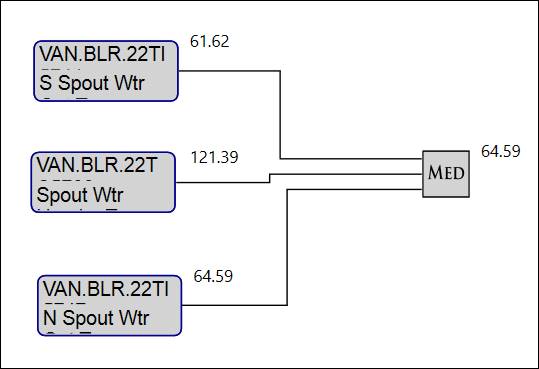
Description: Accepts two or more inputs. Outputs the maximum input value.
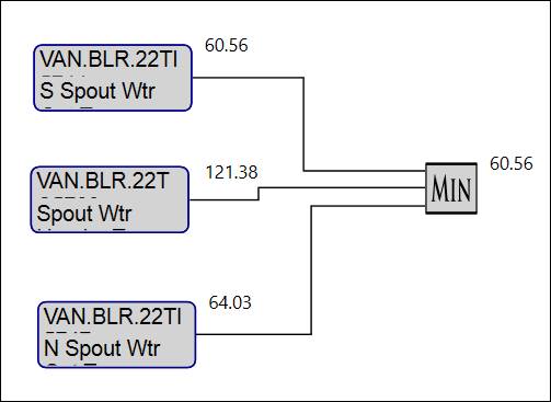
Description: Accepts two or more inputs. Outputs the minimum input value.
Description: Accepts two inputs. Output is the product of the inputs.
Description: Accepts one input. If the input value provides an alarm condition of true, then outputs an alarm condition of false. If the input value provides an alarm condition of false, then outputs an alarm condition of true.
Description: Accepts two or more inputs. If at least one input provides an alarm condition of true, then the output is an alarm condition of true. If all inputs provide an alarm condition of false, then the output is an alarm condition of false.
Description: Accepts two or more inputs. Outputs the difference between the maximum value and the minimum value.
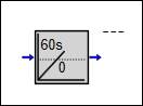
Description: Accepts one input. If the rate of change (slope) of the input value exceeds the specified threshold, then the output is an alarm condition of true.
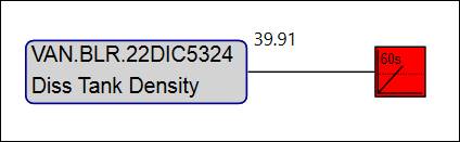
Configuration: Specify the interval of rate calculation in seconds and the threshold value.
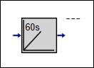
Description: Accepts one input. Outputs the rate of change (slope) of the input value using a best fit statistical method.
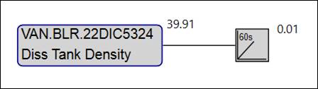
Configuration: Specify the interval of rate calculation in seconds.
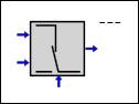
Description: Accepts three inputs, A, B, and C. If input C provides an alarm condition of true, then the output is the value of input B. If input C provides an alarm condition of false, then the output is the value of input A.
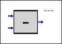
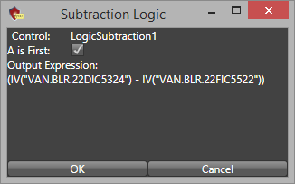
Description: Accepts two inputs. Output is the difference of the inputs. By default the first (top/A) input is the minuend, and the second (bottom/B) input is the subtrahend.
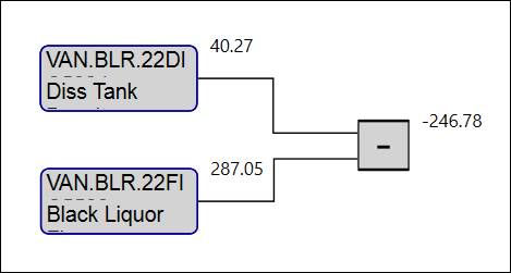
Configuration: Specify whether the first input is the minuend or the subtrahend.
Description: Accepts two or more inputs. Output is the sum of the inputs. The input sign can be specified in the control’s configuration.
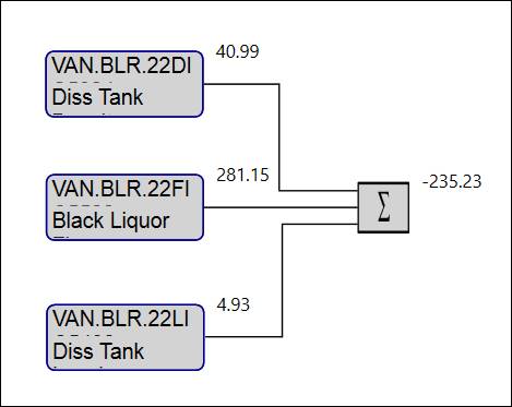
Configuration: Specify the sign of the input values.

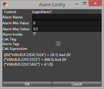
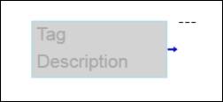
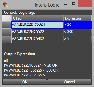
Description: Accepts two or more tag values as the inputs. Drag and drop multiple tags onto the control. If the expression defined in the control’s configuration evaluates to true, then the output is an alarm condition of true. If the expression defined in the control’s configuration evaluates to false, then the output is an alarm condition of false.
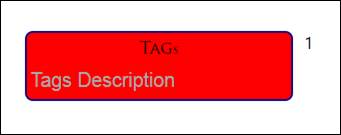
Double-click the control to enter a description of the expression logic.
Configuration:
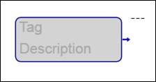
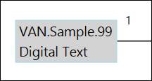
Description: Accepts one tag value as the input. Drag and drop the tag onto the control. Output is the tag’s value.
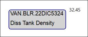
The fully qualified tag name and tag description automatically populate on the control. Double-click the control to modify the tag description.
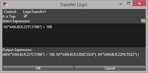
Description: Accepts two inputs, A and B. An expression must be specified in the control’s configuration. If the expression evaluates to true, then the output is input A. If the expression evaluates to false, then the output is input B. If the input value is numeric, then the output is numeric. If the input value is an alarm condition, then the output is an alarm condition.
Expression evaluates to true:
Expression evaluates to false:
Expression evaluates to false:
Expression evaluates to true:
Configuration: Specify the expression to be evaluated and whether the top input is the A input. Click the tag icon to open the Tag Browser and drag and drop tags into the expression field.